Leased and operated by MJM Acoustical Consultants Inc. (1992-2006)
Domtar Acoustical Laboratory
In Seneville, Quebec, Canada
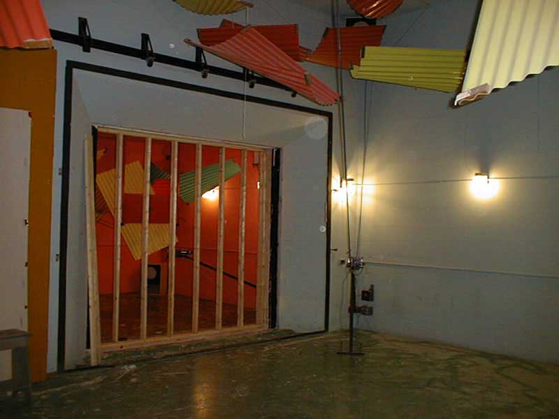
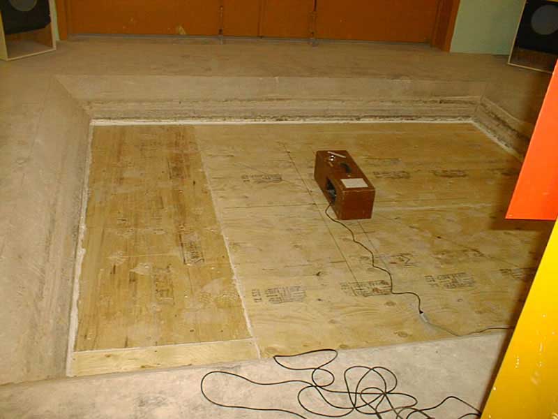
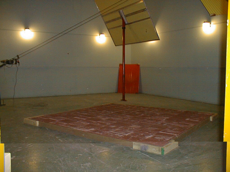
The facility consisted of a control room and three reverberant rooms which were structurally decoupled from one another. Both the source room (90 m3) and the receiving room (255 m3) were equipped with rotating diffusers to maintain a proper reverberant field; all three rooms were also equipped with stationary diffusers. For airborne and impact measurements on floor/ceiling assemblies, the receiving room was located below the impact room (see figure 1 for more details). The dimensions, volume, construction, and weight of each room and the number of springs on which they rest (for the source and receiving room) appear in the paragraphs below, along with the dimensions of the test openings.
The measurements were controlled by a microcomputer interfaced with a Larson Davis 2800 or 2900 real time frequency analyser, to which were connected two Brüel & Kjær type 4155 condenser microphones mounted on two Larson Davis type 900 B preamplifiers; one microphone located in the source room and the other located in the receiving room. There were 10 microphone positions in each reverberant chamber; a stepping motor and a transverse chain carrier located along one diagonal of the room move the microphone from position to position. The microphones have been calibrated before and after each test with a Brüel & Kjær type 4230 piston phone calibrator. The sound pressure levels measured at each position are equivalent levels integrated over a period of more than 20 seconds.
You will find below the dimensions and characteristics of the reverberation chambers:
Source Room
- Room dimension 14'5"x17'10"x11'2" (4.39mx5.44mx3.40m)
- Room surface area 1230pi² (114.27m²)
- Room volume 3190 pi³ (90.33 m³)
- Room weight 97 imperial tons (89 metric tons)
- Wall thickness 1' (305 mm)
- Number of springs 208
Receiving (Reverberation) Room
- Room dimension 21'3"x26'2"x16' (6.48mx7.98mx4.88m)
- Room surface area 2 620pi² (243.41m²)
- Room volume 9 020 pi³ (255.42 m³)
- Room weight 197 imperial tons (178.7 metric tons)
- Wall thickness 1' (305 mm)
- Number of springs 432
Impact Room
- Room dimension 16'5"x18'6"x11'4" (5.00mx5.64mx3.45m)
- Room surface area 1 400pi² (130.1m²)
- Room volume 3 440 pi³ (97.41 m³)
- Wall thickness 1' (305 mm)
Test Openings
- Walls 10'x9' (3.05mmx2.74mm)*
- Floors and ceilings 8'x10' (2.44mmx3.05mm)*
*Note : A filler wall may be constructed to accommodate smaller samples.
Tests most often performed
Sound transmission loss provided by building elements (ASTM E 90)
The method described in the ASTM E90 Standard to measure the sound transmission loss of a building element (floor or wall) consists of installing this element between two reverberant rooms (the source room and the receiving room) which are structurally independent from one another, in a frame which is itself structurally independent from the reverberant rooms. A broadband steady state noise is generated in the source room and its level is measured; the portion of the sound which has been transmitted through the element tested is also measured inside the receiving room. Also measured is the reverberation time in the receiving room which will be used to determine the sound absorption in this room. By subtracting the sound pressure level measured in the receiving room from that measured in the source room, one can calculate the Noise Reduction (NR) values for each 1/3 octave band from 125 Hz to 4000 Hz. The sound transmission loss (TL) values are obtained by normalizing the NR values in function of the surface of the building element tested and of the absorption in the receiving room. The TL values are then classified as per ASTM E 413 to obtain the Sound Transmission Class (STC), which is a single number rating allowing to quickly compare the noise isolation provided by building elements. The higher the rating, the better the performance of the element tested.
Impact noise isolation provided by floors (ASTM E 492)
The method described in the ASTM E 492 Standard to measure the impact isolation provided by a floor/ceiling assembly consists in installing this assembly between two reverberant rooms (the source room located above and the receiving room located below) which are structurally independent from one another, in a frame which is structurally independent from the receiving room. A standardized tapping machine is then installed on the floor and adjusted to provide a hammer drop of 40 mm. The sound pressure levels generated by the tapping machine are then measured in the receiving room located below the floor/ceiling assembly at the 10 microphone positions inside the receiving room, for the four tapping machine positions required by the Standard. The reverberation time is also measured inside the receiving room to evaluate the sound absorption. The Impact Sound Pressure Levels measured for frequencies ranging from 100 to 3150 Hz are then normalized in function of 10 metric sabins of absorption to obtain the Normalized Impact Sound Pressure Levels (NISPL’s) and classified as per ASTM E 989 to obtain the Impact Insulation Class (IIC) rating. The IIC rating is a single number rating allowing acousticians and construction professionals to quickly compare the impact isolation provided by different floor/ceiling assemblies. The higher the rating, the better the performance of the assembly.
Sound absorption coefficients provided by construction materials (ASTM C 423)
Sound absorption tests were conducted inside the large reverberation chamber (255 m3) as prescribed by ASTM C 423, on materials installed as prescribed by ASTM E 795. The surface area of the samples must be at least 48 sq. ft. but preferably 72 sq. ft, which is customary and highly recommended. The test procedure consists in measuring the reverberation time inside the reverberation room with and without the sample installed inside. Using the measured reverberation times one can calculate the quantity of sound absorption provided by the sample tested expressed in metric sabins. Dividing the number of metric sabins by the surface area of the sample in square meters provides the sound absorption coefficient of the material tested; the higher the coefficient, the more sound absorptive is the material.
Other tests in laboratory conditions
- ASTM E 596 Standard Test Method for Laboratory Measurement of the Noise Reduction of Sound-Isolating Enclosures
- ASTM E 1222 Standard Test Method for The Laboratory Measurement of the Insertion Loss of Pipe Lagging Systems
- ASTM E 1408 Standard Test Method for Laboratory Measurement of the Sound Transmission Loss of Door Panels and Door Systems
- ISO 140/3 Mesurage en laboratoire de l’isolation aux bruits aériens des éléments de construction
- ISO 140/6 Mesurage en laboratoire de l’isolation des sols aux bruits de chocs
- ISO 140/8 Mesurage en laboratoire de la réduction de la transmission des bruits de chocs par les revêtements de sol sur plancher normalisé
- ISO 354 Mesurage de l’absorption acoustique en salle réverbérante
- ISO 3741 Détermination des niveaux de puissance acoustique émis par les sources de bruits – Méthodes de laboratoire en salles réverbérantes pour les sources à large bande
- ISO 3742 Détermination des niveaux de puissance acoustique émis par les sources de bruits – Méthodes de laboratoire en salles réverbérantes pour les sources émettant des fréquences discrètes et des bruits à bandes étroites